A glance into boolean algebra
Truth tables and digital circuits
What is and why is it important?
Computers are made of digital circuits that work only with the values 0 and 1, not with decimal values like us humans. This representation is called binary and it requires ways to convert a number from decimal to binary and vice versa. Furthermore, it requires ways to elaborate these numbers, such as making additions and subtractions. In this article we won’t explore the world of binary numbers per se, but how binary values are elaborated.
Boolean algebra gives us all the tools to do just so.
A variable X is boolean when it can take only 0 or 1 as values. These values can also be seen, respectively, as false or true.
Logical operators
There are three main operators: NOT, AND, and OR.
NOT
The negation operator changes a binary value. For example, the value 1 will become 0, and the value 0 will become 1. This works perfectly because there are only two possible values.
The operator is often represented with one of these symbols: ~, ¬, !.
To show better how the NOT operator works we can use a truth table. A truth table shows every possible combination of the starting variable and the result of the operations. We will use them in every operation we are going to see.
Y = !A 
AND
The AND operator takes two binary values, A and B, as input and its result Y is True (1) only when both the input values are True. Otherwise, Y is False.
The operator is called also logical product and is represented with a · :
Y = A · B
OR
The OR operator takes two binary values, A and B, as input and its result, Y, is True when at least one of the two values are True. In the case that both are False (0), Y is too.
The operator is called also logical sum and is represented with a +:
Y = A + B
So now that we had a look into these operators we can start writing our own functions or digital circuit. Let’s take a look at the circuit below. This must be read from left to right, because the input values - A, B, and C - are on the left, and the result value - Y - is on the right. The values pass through the different blocks, the different digital operators, and we would like to know what is the result Y as a function of the input values.

Looking at the circuit we can write the function:
Y = (!A · B) + CTo see all the different possible cases we can have, depending on the input values, we need to write down the truth table. This can be laborious. We need to elaborate case per case and determine the various result value.
Instead of instantly looking for Y, we can first find the value of X, an arbitrary point I decided to divide the operations I have to make.

This is the truth table before making any operation:

We can complete easily enough the X column:
X = !A · B
And now we can calculate Y:
Y = X + C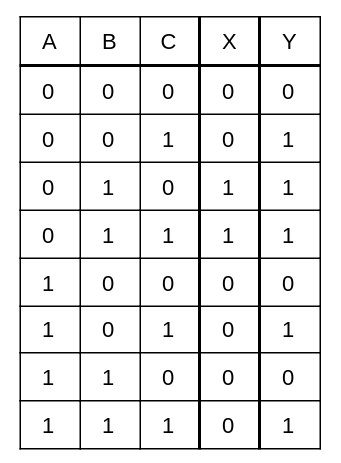
Now we can read a circuit and determine the truth table!
These operators have properties just like sum and product have. If you wanna read more about it:
Thank you for reading this article, I hope it helped you!
